Basic Overdrive Pedal
Now we'll look at how to construct a 'basic' overdrive pedal. There's nothing particularly fancy or special about this pedal, but it will
function as a nice overdrive (actually its maybe somewhere in between overdrive and distortion...) with some good tunability.
It might look quite similar to the MXR Distortion+, but with a few changes in
component sizes and configurations.
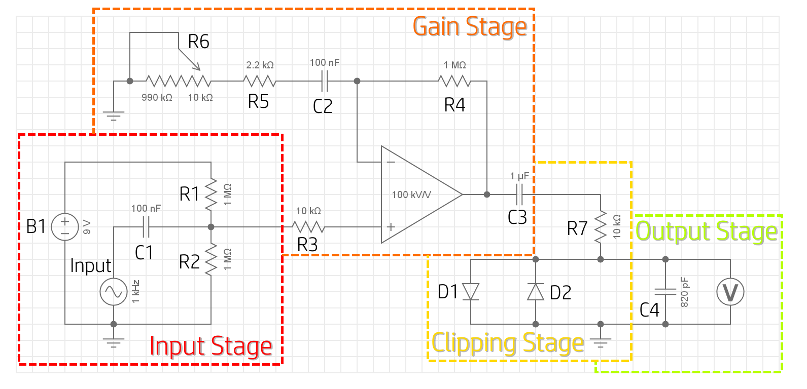
Here's a quick look at our full schematic. This is what we're aiming to build - we'll run through each of these four sections (input, gain
, clipping, output) individually.
We'll start things nice and simple, looking at the overdrive circuit with one control (gain), and no 'on/off' switch. Clearly this isn't much use - if you decide you don't want overdrive... well you can only have overdrive. However, this way we can start off simple, then make some mods afterwards to give it some more functionality or a different sound.
Ingredients
For this pedal, you'll need the following:| Jack Socket x2 |  |
Resistor
|
 |
Capacitor
|
 |
| Operational Amplifier x1 |  |
Potentiometer
|
 |
| Diode x2 |  |
| \(9V\) Battery x1 |  |
Method
The input stage
We're using a single, \(9V\) battery to power the operational amplifier in this pedal, an active component. The op-amp can therefore output any voltage between \(0V\) and \(9V\). Our input is centred around \(0V\), so in our 'perfect sine wave' simplification of the audio signal, half of our signal is at a voltage below \(0V\). If our op-amp tries to amplify a negative voltage, it won't be able to, since the output can't go below the negative supply (\(0V\)).
It's simple enough to get around this, though! If we 'shift' our input signal so that it's no longer centred around \(0V\), but is instead centred around \(4.5V\), we can take advantage of the full op-amp output range. This 'shift' is known as a DC bias. As we're using a battery for this pedal, we can use a slightly simpler circuit than if we were using a wall-wart supply, as batteries aren't as noisy as wall supplies.
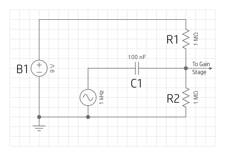
Looks nice and easy, right? Let's have a quick chat about whats going on here.
R1 and R2 form a voltage divider. Both resistors
are the same size (\(1M\Omega\)), and so the supply voltage is evenly split to give the same drop over each: \({9V \over 2}=4.5V\).
Adding a \(4.5V\) DC bias to our input signal (represented as an AC voltage source in the schematic), basically means adding
\(4.5V\) to our signal at every point in time, so that it has the same shape and peak to peak voltage level, but so it is
oscillating around a centre voltage of \(4.5V\) instead of \(0V\).
However, we can't simply directly connect our source to the junction between R1 and R2 - if we did this, the junction voltage would just be equal to the input voltage, and B1 would be able to force current back into our guitar. This is because our guitar has a low impedance, and so DC current would easily make it's way back to the pickups. To prevent this, we use a coupling capacitor, which blocks the DC current from flowing back into our guitar (due to it's high impedance for low (or zero) frequency signals), but allows the AC signal into our pedal circuit.
Since C1 presents an (essentially) infinite resistance to the DC current supplied by B1, no current will flow this way, and it's like there's no connection at all. This means the DC current is determined by R1 and R2 in series as \(I = {V \over R} = {9V \over 1M \Omega + 1M \Omega} = 4.5 \mu A\). Depending on how comfortable you are with capacitors, you may know something about how they introduce a phase shift (this is where complex numbers come into our impedance discussions). For now, we'll just ignore the phase shift and note that our AC waveform is present at our voltage divider junction (this is fine because all the phase shift is doing is flipping our positive and negative half cycles, and so the following discussion will still be true).
If we have a \(500mV_{peak}\) signal at our junction, it will see R1 and R2 in parallel, and so with an effective resistance of \({1 \over {1 \over 1M\Omega} + {1 \over 1M\Omega}} = 500k\Omega\). This means the signal current peaks at \({500mV \over 500k\Omega} = +/-1\mu A\). In the positive half cycle, our source pushes current down through R2 to ground. The total current through R1 and R2 must remain at \(9 \mu A\) (in order to still drop \(9V\) total across the network), and since we're adding \(1 \mu A\) from our signal, the current through R2 increases by \(0.5 \mu A\) to \(5 \mu A\), whilst the current through R1 decreases by \(0.5 \mu A\) to \(4 \mu A\). We now have \(V_{R2} = 5 \mu A \times 1 M \Omega = 5V\), and \(V_{R1} = 4 \mu A \times 1 M \Omega = 4V\). The opposite will be true for the negative half cycle. We measure the voltage between the junction and ground (which is equal to the voltage dropped across R2) and this is the voltage that is passed to the gain stage. It is now osciallting between \(4V\) and \(5V\) - this is our biased input signal.
The size of C1 isn't that important, and can be decided based on personal preference. A larger capacitor will give you a bassier response, a smaller one will cut your bass a little lower. This is because C1 and R2 are forming a high-pass filter. Typically you'll see film capacitors used in coupling applications because they have lower leakage than electrolytic capacitors.
And that's our input stage! Simple, right? Now we have a DC-biased input signal present at the junction of the voltage divider, ready to be sent into the gain stage of our pedal.
The gain stage
We're using an operational amplifier to amplify our signal. We're going to have our op-amp in a non-inverting configuration, meaning that the output will have the same polarity as the non-inverting (\(+\)) input, but a greater amplitude. This stage is necessary to allow the diodes to properly clip the signal in the clipping stage. The output from our guitar might typically be less than \(+/-0.5V\), and the diode network will only start clipping when the magnitude exceeds the forward-bias voltage drop of the configuration (usually above \(0.7V\)). By amplifying our signal, we then allow the diodes to actually clip the peaks and troughs to create the distorted sound we're looking for.
Let's look at the circuit section.
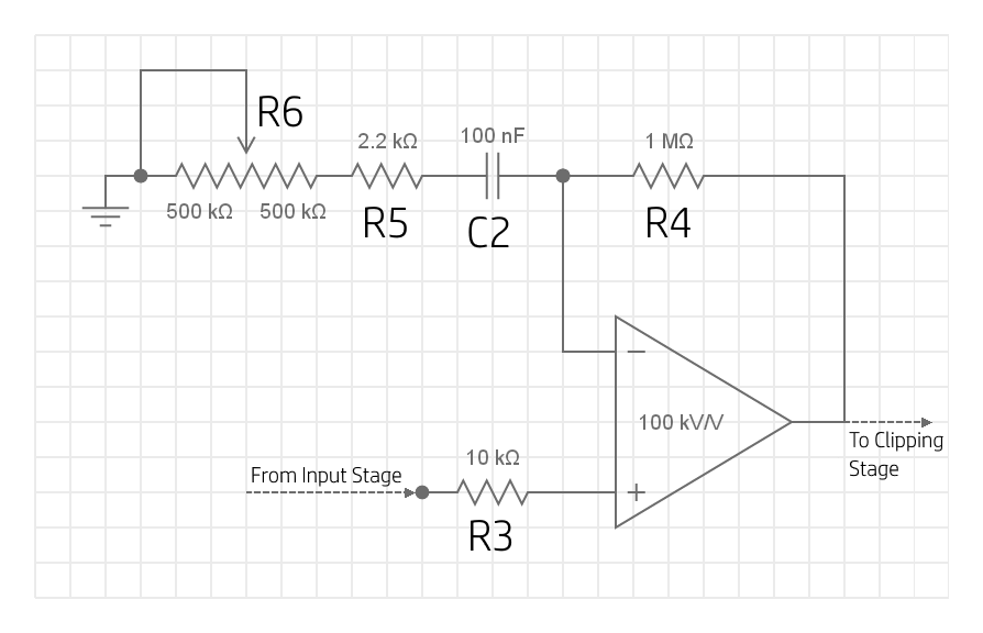
Simply put, the operational amplifier takes our input signal at its non-inverting (\(+\)) input, and outputs an amplified version of this. To do this, the op-amp must be connected in such a way that it creates a non-inverting amplifier. To achieve this, we connect the output of the op-amp back to the inverting (\(-\)) input via a voltage divider. We already covered non-inverting amplifiers in detail here, and so we wont dwell on the specifics, but all you need to know is that the values of R4, R5 and R6 define the gain of the amplification stage through the relationship: \(gain = 1+{R4 \over R5 + R6 + X_C}\), where \(X_C\) is the impedance of C2 - we'll discuss this component a little further down. We could make a fixed-gain amplifier by using fixed resistances here, but where's the fun in that? If we instead use a potentiometer in one of these positions, we can control the gain of the amplifier just by twisting a knob - neat!
In our circuit, R6 is a potentiometer with maximum resistance of \(1M\Omega\). We connect the wiper to the grounded leg
of the pot so that the ground-side portion of the pot is shorted, and what we have is essentially just a variable resistor. This
variable resistor allows us to swing our gain between \(1+{1M\Omega \over 1M\Omega + 2.2k\Omega} \approx 2\) and
\(1+{1M\Omega \over 2.2k\Omega}=455.5\).
Note that this upper value varies with the minimum resistance possible on your potentiometer, but the point is that it's
very high. R5 is acting as a gain limit. If we decrease the size of R5, we increase the maximum possible gain.
However, without it, things start to get a bit screechy and painful, so just play around and find something you like!
Also, we've ignored the capacitance here for reasons we will discuss below.
It's quite a good idea (though not a necessity) to use a 'reverse-log' pot for R6. We discussed reverse-log pots here, but
the key thing to know is to understand that a reverse-log pot better distributes our gain across the motion of the shaft.
C2 is quite an important component in this circuit. Remember how we offset our signal up to \(4.5V\) in the input stage? Well now we have a signal that has both DC and AC components. The gain of the op-amp, if set only by the resistances, would be the same for the AC and DC components, and so our offset would be amplified too, according to the gain of the configuration. This risks amplifying our DC component so much that it saturates at the top of the output range (\(9V\)), and we lose the top-half of our waveform. We can re-visit the gain calculation for DC components (\(gain = 1+{R4 \over R5 + R6 + X_C}=1+{R4 \over R5 + R6 +{1 \over 2 \times \pi \times f \times C}}\)) and note that \(X_C\) is really high for DC components, meaning that for DC components, the gain approaches \(1\). The capacitor should also be large enough that it doesn't provide a high impedance to our AC frequencies of interest, too, and significantly drop our AC gain for these frequencies.
R3 is simply our current limiting resistor, and just serves as protection for our op-amp against any surges of current that might damage the semiconductor junctions within. \(10k\Omega\) is a pretty standard value.
The clipping stage
To actually create the 'distorted' sound, we can use a neat little trick using diodes.
To recap: a diode will conduct current in one direction, and block it in the other. In order to conduct current in the forward-bias direction, the voltage between the two legs of the diodes must exceed what is called the 'forward-bias voltage'. Once this potential difference is achieved, the diode begins to conduct current. Now, once the diode is conducting current, the voltage drop between it's legs remains almost constant for any amount of current flow through the diode. For example, a silicon diode will drop \(\approx0.7V\) for any amount of current flowing through it, and so the anode will be at a voltage that is \(0.7V\) higher than the cathode.
Let's think about a slightly simpler case first. Lets say we have an AC signal connected in series with a resistor and a diode.
Before the voltage across the diode reaches \(0.7V\), the diode isn't conducting and so there's no current flow in our circuit. Since
there's no current flowing through the series resistance, there's no voltage drop across the resistor (ohms law), and so the measured
output voltage (the blue line in the image below) is equal to the input voltage).
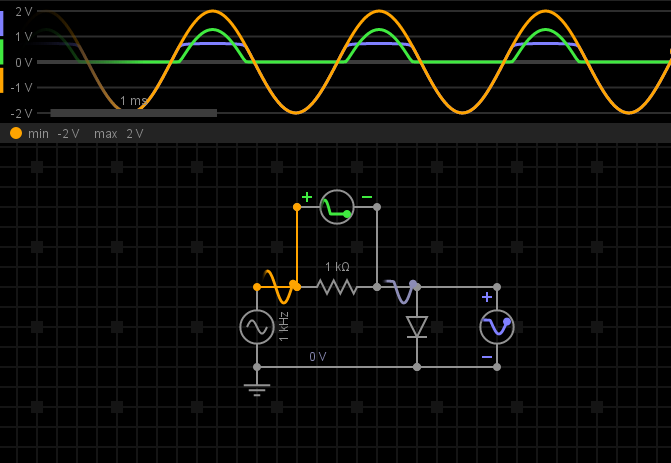
Once the input voltage reaches \(0.7V\), the diode begins to conduct current. Since the cathode is connected to ground, this actually means that the anode will be at \(0V+0.7V=0.7V\) whenever the diode is conducting. As the input voltage increases past \(0.7V\) the diode conducts a larger current. Since the resistor is in series with the diode, it also conducts more current, and so the voltage drop across the resistor increases - the voltage drop across the resistor will be \(V_{in}-0.7V\), so that the voltage drop across the diode when conducting is constant.
Now back to our overdrive circuit, and this mechanism can be used to 'clip' our signal. As you can see in the figure above, the
output voltge (the blue line), is the same as the input voltage (the orange line), but with the peak clipped to \(0.7V\). We want
to do this to both the positive and negative half cycles of our waveform.
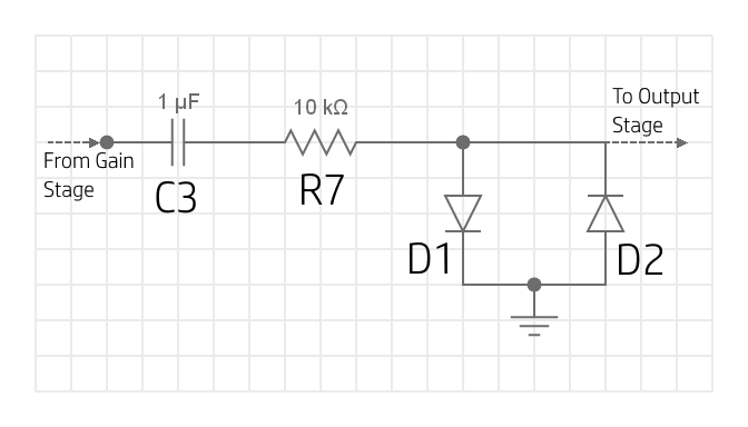
Connecting the anode of a diode to our signal and the cathode to ground allows us to clip the positive half of the waveform as we
discussed above. Then adding a second diode in parallel with this, but with the cathode on our signal and the anode to ground, allows
us to clip the negative half of the waveform. This configuration results in symmetric clipping (the waveform is clipped at the same
amplitude for the positive and negative half cycles), and is achieved by diodes D1 and D2 in our
clipping stage schematic. The result is then a truncated waveform, similar to those we saw when
discussing how distortion works. In this configuration, the signal is hard-clipped,
which might actually sound more like distortion than overdrive (note, however, that the clipping won't be as severe as we saw in
the distortion discussion, as real components aren't quite capable of this kind of performance).
The output stage
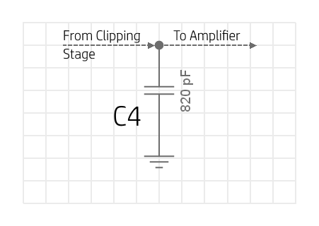
As we discussed, this version of the circuit is nice and simple, so there is very little going on at our output right now.
All we've done is added a capacitor in parallel with our clipping diodes and our output, and this is working with our current
limiting resistor R6 to create a low-pass filter.
Using the cut-off frequency equation \(f_c={1 \over 2 \times \pi \times R \times C}\), we see that a larger capacitor will give
us a lower cutoff frequency, cutting the treble a bit. Again, this capacitor is a good component to experiment with - try a few
different values and find something you like the sound of. For our \(10k\Omega\) resistor, \(800pF\) gives us a cutoff frequency
around \(20kHz\), so anything larger than this will noticeably cut our trebles. \(820pF\) is a standard capacitance value, so
this is what we've gone for here, but you can also combine
capacitors in series or parallel
to get more specific values.
When we start looking at how we can modify this circuit, we'll add a volume and tone control into the output stage so we have flexibility over our sound without having to change all our components.
The full assembly
If we put all of this together, we have what is essentially the simplest overdrive pedal that we can make. No switches, one control,
and it sounds relatively unremarkable. It still does a decent job though!
Here we're representing our input as an AC voltage source, and our output as a voltmeter, but obviously in our actual circuit this would be where we connect our input and output jack sockets.
Modifications
Volume control will act as tone if coupling cap not high enough (consider f_c)
Tone control
alters sound:
higher output cap value is cutting more treble & volume
log pot maybe better?
different diodes & diode arrangements (asymmetric, series diodes, etc.) different sound. Try difference between hard & soft clip
gain on op-amp alters output